Saturday, December 24, 2016

PIC18f - Dual PWM, sinusoidal PWM

Generating sine wave signal using PIC1xf series is a common project in internet but most of the source code is written in assembly language. Assembly language is good and efficient but it is not portable as C language.

I found a series of tutorials at tahmidmc blog.

The blog explains the sine wave pwm generation from head to toe.

Always start with tutorials for learning.

The key of sine wave is the sine wave duty cycle constants,
tahmidmc has created a useful program to generate sine wave constants. 
It is a handy and easy to use but it requires installation which i do not like.

How TO Use the Software
There are two types of sinusoidal pwm, unipolar pwm and bipolar pwm.
For unipolar pwm, only need two pwm to form sinusoidal wave.
For bipolar pwm, need four pwm to form sinusoidal wave but the DC voltage needed only Vpeak, while unipolar pwm need DC voltage which is double of Vpeak.


At smart sine, for unipolar pwm, you need to add offset to get full sine wave.
A simple example, would be as follow:

Use the 32 samples for better viewing, purpose, but the sample entries can be changed to get desired sine wave frequency.

Example, 
PWM frequency: 20kHz, sine wave frequency = 50Hz.
Sample = (PWM frequency) / (sine wave frequency)
             = (20 000) / (50) = 400


Always tune the PWM frequency to get desired sine wave frequency as the sample entries can be changed.


Now for the PWM settings - ECCP1CON (8 bits)
P1M1:P1M0: Enhanced PWM Output Configuration bits
10 = Half-bridge output: P1A, P1B modulated with dead-band control; P1C, P1D assigned as port pins
DC1B1:DC1B0: PWM Duty Cycle Bit 1 and Bit 0
PWM mode:
These bits are the two LSbs of the 10-bit PWM duty cycle. The eight MSbs of the duty cycle are found in CCPR1L.
CCP1M3:CCP1M0: Enhanced CCP Mode Select bits
1100 = PWM mode: P1A, P1C active-high; P1B, P1D active-high
1101 = PWM mode: P1A, P1C active-high; P1B, P1D active-low
1110 = PWM mode: P1A, P1C active-low; P1B, P1D active-high
1111 = PWM mode: P1A, P1C active-low; P1B, P1D active-low


For dual mode pin assignment,


To skip the datasheet details, it is good to read block diagram,

Half bridge PWM output

The PIC18f enhanced PWM has dead band control which is good for high side and low side switch control. Power transistor has faster switch on time but slower switch off, if both high and low side is switched at the same time, a very high current (shoot-through current) may flow through both power switches, shorting the bridge supply.
Dead band delay allow switch to fully turned off before switch on another power transistor.

ECCP1DEL: PWM DEAD-BAND DELAY REGISTER
PDC6:PDC0: PWM Delay Count bits
Delay time, in number of FOSC/4 (4 * TOSC) cycles, between the scheduled and actual time for a PWM signal to transition to active.


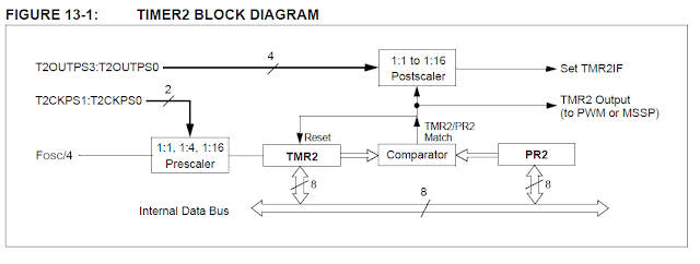
Another important module associated with PWM is timer2. Just for reference, 


Now we have all the details need to write the code:


  1
  2
  3
  4
  5
  6
  7
  8
  9
 10
 11
 12
 13
 14
 15
 16
 17
 18
 19
 20
 21
 22
 23
 24
 25
 26
 27
 28
 29
 30
 31
 32
 33
 34
 35
 36
 37
 38
 39
 40
 41
 42
 43
 44
 45
 46
 47
 48
 49
 50
 51
 52
 53
 54
 55
 56
 57
 58
 59
 60
 61
 62
 63
 64
 65
 66
 67
 68
 69
 70
 71
 72
 73
 74
 75
 76
 77
 78
 79
 80
 81
 82
 83
 84
 85
 86
 87
 88
 89
 90
 91
 92
 93
 94
 95
 96
 97
 98
 99
100
101
102
103
104
105
106
107
108
109
110
111
112
113
114
115
116
117
118
119
120
121
122
123
124
125
#include <p18f4553.h>

//******************************************************************************
//  CONFIG
//******************************************************************************
        #pragma config PLLDIV   = 5         // (20 MHz crystal on PICDEM FS USB board)
        #pragma config CPUDIV   = OSC1_PLL2  
        #pragma config USBDIV   = 2         // Clock source from 96MHz PLL/2
        #pragma config FOSC     = HSPLL_HS
        #pragma config FCMEN    = OFF
        #pragma config IESO     = OFF
        #pragma config PWRT     = OFF
        #pragma config BOR      = ON
        #pragma config BORV     = 3
        #pragma config VREGEN   = ON      //USB Voltage Regulator
        #pragma config WDT      = OFF
        #pragma config WDTPS    = 32768
        #pragma config MCLRE    = ON
        #pragma config LPT1OSC  = OFF
        #pragma config PBADEN   = OFF
//      #pragma config CCP2MX   = ON
        #pragma config STVREN   = ON
        #pragma config LVP      = OFF
//      #pragma config ICPRT    = OFF       // Dedicated In-Circuit Debug/Programming
        #pragma config XINST    = OFF       // Extended Instruction Set
        #pragma config CP0      = OFF
        #pragma config CP1      = OFF
//      #pragma config CP2      = OFF
//      #pragma config CP3      = OFF
        #pragma config CPB      = OFF
//      #pragma config CPD      = OFF
        #pragma config WRT0     = OFF
        #pragma config WRT1     = OFF
//      #pragma config WRT2     = OFF
//      #pragma config WRT3     = OFF
        #pragma config WRTB     = OFF       // Boot Block Write Protection
        #pragma config WRTC     = OFF
//      #pragma config WRTD     = OFF
        #pragma config EBTR0    = OFF
        #pragma config EBTR1    = OFF
//      #pragma config EBTR2    = OFF
//      #pragma config EBTR3    = OFF
        #pragma config EBTRB    = OFF

const rom unsigned int unipolar_32_sine_wave_constant [32] = {
511, 611, 707, 795, 872, 936, 983, 1012, 1022, 1012, 983, 936, 
872, 795, 707, 611, 511, 411, 315, 227, 150, 86, 39, 10, 0, 10, 
39, 86, 150, 227, 315, 411
};

struct pwm_settings
{
 unsigned char mode;
    unsigned int duty_cycle;
    unsigned int frequency;
};

struct pwm_settings pwm;

unsigned char counter=0;


void main()
{
 RCONbits.IPEN=1;
 
 // set the dual mode
 ECCP1CONbits.P1M = 0b10;
 ECCP1CONbits.CCP1M = 0b1101;

 // set the pin output
 TRISCbits.TRISC2 = 0;
 TRISDbits.TRISD5 = 0;

 //---------------------------------------------------
 // set timer 2
 T2CONbits.T2CKPS = 0b00;
 T2CONbits.TOUTPS = 0b0000;
   T2CONbits.TMR2ON = 0;  // STOP TIMER2 registers to POR state
 PIE1bits.TMR2IE = 0;   // Disable Timer2 overflow interrupts
   PR2 = 0xFF;            // Set period
 
 //---------------------------------------------------
 // set dead-bank delay
 ECCP1DELbits.PDC = 0b000000;
 
 CCPR1L = 0xFF;
 ECCP1CONbits.DC1B = 0b00;
 
 INTCONbits.GIEH=1;
 T2CONbits.TMR2ON = 1;  // Enable TIMER2 registers to POR state
 PIE1bits.TMR2IE = 1;   // Enable Timer2 overflow interrupts
}

//----------------------------------------------------------------------------
// High priority interrupt vector
void InterruptHandlerHigh() ;
#pragma code InterruptVectorHigh = 0x08
void InterruptVectorHigh(void) {
  _asm
    goto InterruptHandlerHigh //jump to interrupt routine
  _endasm
}

//----------------------------------------------------------------------------
// High priority interrupt routine
#pragma code
#pragma interrupt InterruptHandlerHigh
//
// Timer0 overflow
void InterruptHandlerHigh() 
{
    if (PIR1bits.TMR2IF)
  PIR1bits.TMR2IF = 0;

 counter++;
 if(counter >= 32) counter=0;
 pwm.duty_cycle = unipolar_32_sine_wave_constant[counter];

/* 
 Duty cycle PWM port1
*/ 
 CCPR1L = (unsigned char) (pwm.duty_cycle >> 2);
 ECCP1CONbits.DC1B = (unsigned char) (pwm.duty_cycle);
}

Result:


Saturday, December 17, 2016

PIC18f - 10 bits PWM

After I have my hand on kingst logic analyser, I suddenly realise there a lot of things that I can do. I can write a simple coding and check the output signal using logic analyser. It makes the development way easier.

"Previously, I was lack of this kind of equipment for verification purpose." - no more excuse for myself and start coding.

I decide to try on PIC18f PWM, PWM is widely used in power converter control to boost / buck voltage or convert DC voltage to AC voltage.

PWM also generally adapted to emulate DAC in order to generate SINE wave, sawtooth wave.


Before started, always good to look in datasheet and familiar with register first.

1. PWM FREQUENCY CALCULATION
   The equation is pretty much self explainable.


2. REGISTER 15-1: CCPxCON: STANDARD CCPx CONTROL REGISTER
bit 5-4:
PWM mode:
These bits are the two LSbs (bit 1 and bit 0) of the 10-bit PWM duty cycle. The eight MSbs of the duty cycle are found in CCPR1L.
bit 3-0:
CCPxM3:CCPxM0: CCPx Module Mode Select bits:
11xx = PWM mode

3.If you want to prescale your FOSC, please take note on this
   PWM Period = [(PR2) + 1] • 4 • TOSC • (TMR2 Prescale Value)

4. For prescaling the at Timer 2.
    T2CON: TIMER2 CONTROL REGISTER
bit 1-0
T2CKPS1:T2CKPS0: Timer2 Clock Prescale Select bits
00 = Prescaler is 1
01 = Prescaler is 4
1x = Prescaler is 16


I always clock my PIC18f at 48Mhz because I want the maximum performance and I want the clock frequency can be applicable to all projects so that I dont have to change the frequency all the times.

Using equation for note 1:
FPWM = FOSC / (4(PR2 + 1))
my maximum frequency is 46875 where PR2 = 255, FOSC = 48,000,000.

PR2 = 255, mean that I can have duty cycle of 10 bits resolution.

For the duty cycle, I have 8 MSB at CCPR1L, 2 LSB at CCP1CON,
I do like following:

1
2
3
4
      pwm_h = (unsigned char) (duty_cycle >> 2);  
      CCPR1L = pwm_h;  
      pwm_l = (unsigned char) (duty_cycle << 4);  
      CCP1CON = (CCP1CON & 0xCF) | (pwm_l & 0x30);


Basically, we have everything we need, now for the whole code:

 1
 2
 3
 4
 5
 6
 7
 8
 9
10
11
12
13
14
15
16
17
18
19
20
21
22
23
24
25
26
27
28
29
30
31
32
33
34
35
36
37
38
39
40
41
42
43
44
45
46
47
48
49
50
51
52
53
54
55
56
57
58
59
60
61
62
63
64
65
66
        #pragma config PLLDIV   = 5         // (20 MHz crystal on PICDEM FS USB board)
        #pragma config CPUDIV   = OSC1_PLL2  
        #pragma config USBDIV   = 2         // Clock source from 96MHz PLL/2
        #pragma config FOSC     = HSPLL_HS
        #pragma config FCMEN    = OFF
        #pragma config IESO     = OFF
        #pragma config PWRT     = OFF
        #pragma config BOR      = ON
        #pragma config BORV     = 3
        #pragma config VREGEN   = ON      //USB Voltage Regulator
        #pragma config WDT      = OFF
        #pragma config WDTPS    = 32768
        #pragma config MCLRE    = ON
        #pragma config LPT1OSC  = OFF
        #pragma config PBADEN   = OFF
//      #pragma config CCP2MX   = ON
        #pragma config STVREN   = ON
        #pragma config LVP      = OFF
//      #pragma config ICPRT    = OFF       // Dedicated In-Circuit Debug/Programming
        #pragma config XINST    = OFF       // Extended Instruction Set
        #pragma config CP0      = OFF
        #pragma config CP1      = OFF
//      #pragma config CP2      = OFF
//      #pragma config CP3      = OFF
        #pragma config CPB      = OFF
//      #pragma config CPD      = OFF
        #pragma config WRT0     = OFF
        #pragma config WRT1     = OFF
//      #pragma config WRT2     = OFF
//      #pragma config WRT3     = OFF
        #pragma config WRTB     = OFF       // Boot Block Write Protection
        #pragma config WRTC     = OFF
//      #pragma config WRTD     = OFF
        #pragma config EBTR0    = OFF
        #pragma config EBTR1    = OFF
//      #pragma config EBTR2    = OFF
//      #pragma config EBTR3    = OFF
        #pragma config EBTRB    = OFF

#include <p18f4553.h>

void main()
{
 unsigned char pwm_l, pwm_h;
 unsigned int period;

 unsigned int frequency = 46875; // maximum available freq for 10 bits
 unsigned int duty_cycle = 512;  // half duty for testing purpose
 
 period = 0xFF;   // for 10 bits operation

 CCP1CON |= 0b00001100;    //ccpxm3:ccpxm0 11xx=pwm mode  

 TRISCbits.TRISC2 = 0;
//---------------------------------------------------
   T2CONbits.TMR2ON = 0;  // STOP TIMER2 registers to POR state
   PR2 = period;          // Set period
   T2CONbits.TMR2ON = 1;  // Turn on PWM1
 
 pwm_h = (unsigned char) (pwm.duty_cycle >> 2);
 CCPR1L = pwm_h;
 pwm_l = (unsigned char) (pwm.duty_cycle << 4);
 CCP1CON = (CCP1CON & 0xCF) | (pwm_l & 0x30); 
}


Result:
Time to show off my logic analyser:

The readings are located at right side, where the frequency is shown as 45.45kHz, 50% duty cycle. The result is good for me.
45kHz and 10 bits duty cycle is suffice for most application.

Friday, November 25, 2016

kingst logic analyzer LA1002 review

I have always wanted a logic analyzer to make my tools collection complete. There is always china clone logic analyzer flooded the market and it is quit cheap also.

Especially the usbee series and salaea logic clone, they make cheap hardware which is compatible with original software. The review of these logic analyzer are relatively good since you cant argue with the price and it gets the things done.

Although the built is suck but the performance is ok, then it is good for hobbies work. Most of the time, we work on low frequency signal, so a simple signal sniff is good enough.

I have been loitering on baidu (china web browser) and I found one company that design their own logic analyzer and they started to build their reputation in logic analyzer field.

Official website: http://www.qdkingst.com/en

They do come out with a series of products with different capability:
LA5016 (500M/16CH)
LA2016 (200M/16CH)
LA1016 (100M/16CH)
LA1010 (100M/16CH)
LA1002 (24M/8CH) <- I choose this (cheap)

From the picture, you can see the plastic look plus a simple sticker on top the cover.
It come with usb cable and 8 wires ribbon cable,


For starter, it seem like they copying from saleae logic, as they are also using cypress mcu, same as the early version of saleae logic and usbee. (cant remember where I found this information)

Nevertheless, they grow out of the confinement and started to build their own design.

From the review from their website and forum, it seem like they are taking the customer seriously. So I had decided to give it a try.

Let look at the basic overview of the software

I use two channels for i2c analysing. Channel 0 and channel 2.


Then the selection of i2c channel assignment.


Set the trigger direction.

You can see the data received. (yes, i am sending 0, 1, ...9)

But,
maybe due to the cabling they provided or my mistake.
I saw some unwanted spikes.
Update: the pulse is generated by hardware, still have no idea why, saw the similar unwanted pulses in saleae logic.


Despite all, I am satisfy with the result.For debugging usage, it is handy as most products doesn't use very high speed signal bus, so it is suffice for most the conditions (even in product development work).

The software is easy to use and conveniently help you decode the signal to hexadecimal and a few other formats.

Conclusion is good to have. Update: I am using it for most of my projects, really a handy tool, must have.

Additional testing:
PWM signal: PIC18f - Dual PWM, sinusoidal PWMPIC18f - 10 bits PWM
I2C signal: Beaglebone Black I2C Verifying
UART signal: Beaglebone Black - UART


Saturday, October 22, 2016

Linux command tips and tricks

For beginner, it is useful to know a few handy commands which can help to ease the linux learning process.

Linux is too big but there are a few commands which are commonly used.

From the website, vbird has a tutorial or these useful command but it is in Chinese, so i rewrito and simplified it in english.

Telnet
It is same as ssh and the method of using is "telnet xxx.xxx.xxx.xxx" (x is ip address)

Shutdown
"shutdown -h now" - shutdown now
"shutdown -r now" - reboot now
"shutdown -h 20.30" - shutdown at 20.30
"shutdown -h +10" - shutdown after 10 minutes

Reboot
Restart the computer. "reboot"

Cp
Copy file
"cp file1 file2" - copy file1 and rename it to file2

& and [Ctrl] + [z]
These two methods let the task running in background. Useful when you are processing exceptional long file.
Example of using: "make all &" or "make all + [Ctrl] + [z]" - it will run in background.

Fg
Show current running task. "fg"

Ps -aux
Show every task and pid. "ps -aux"

Kill
After we get a task's pid, use kill to terminate the task. "kill xxxx" (x is pid number)

Cd
Change the working directory.
"cd" - back to home
"cd ~" - back to home
"cd .." - up one level directory
"cd /usr/bin" - change the working directory to /usr/bin

Pwd
Show your current working directory. "pwd"

Ls
List out all the files
"ls -l" - list out all the details of files
"ls -a" - list out all files including hidden files.
"ls -al"  list out all files detail including hidden files.

Cat
Show the status of register or content of a file. "cat /sys/bus/usb/devices/1-2/power/control" or "cat abc.txt"

Mkdir
Create a folder. "mkdir abc"

Rm
Delete a file or directory
"rm abc.txt" - delete the abc.txt
"rm -rf abc" - delete the file abc and all contents inside abc

Mv
Move a file to different directory or change the name.
"mv abc.txt ~/" -  move the abc.txt to home
"mv abc.txt efg.txt" - change the name of abc.txt to efg.txt

Find
Useful to find a file. "find /path/name/ -name file_name"

Whereis
From the bash command history, search the particular file. "whereis file_name"

Chmod
Change the nature of a file. "r - 4, w - 2, x - 1". Needed when you want write scripts.
"chmod 755 scripts_name"

Df
List out all memory detail. "df"

Du
List out all file size. "du"

NOT YET FINISHED, WILL ADD IT WHEN I HAVE TIME. MAYBE WILL POLISH IT A BIT

Thursday, September 15, 2016

low cost isolated current sensing IC - ACS710

For low cost isolated current sensing, Allegro hall effect current sensing IC has come into picture. Allegro has produces a series of low cost current sensing IC.

ACS710 has been in market for quite some time and it is suitable for renewable energy application as in described in “AN296110-Current Sensing for Renewable Energy”.

ACS710 has 1 mΩ sensing resistance for low power loss, user selectable overcurrent fault level, provided in surface mount SOIC16 package, operating temperature is from -40ºC to 125ºC.

Best part is no isolated voltage supply is needed. (Save the cost)

Maybe the only drawback is the low voltage isolation.
The voltage isolation characteristics that had been conducted by Allegro.
Test Characteristic
Rating (VAC)
Dielectric Strength Test Voltage (60s)
3000
Working Voltage for Basic Isolation
277

Neverthelss, for most applications, the continuous working voltage of 277VAC is more than enough.

ACS713 is provided in several sensing range such as follow:
Sensing Range (Ampere)
Sensitivity at Vcc=5V (mV/A)
±6
151
±10
85
±12.5
56
±25
28

Supply voltage – 3V to 5.5V.
Signal bandwidth – 120kHz

From the above picture, you can see that for the full operation of 120kHz, filter capacitor of 0.1nF or less is needed. 

Of course, you can increase the filter capacitance, the higher the filter capacitance, the lower the bandwidth. Good point is the RMS noise also significant reduced.

ACS713 has the over-current detection mechanism and the settings/calculation as follow
For the setting of overcurrent detection,
Version 6BB and 10BB, the formula is as follow:
VOC = 1.17 × Sens × | IOC |

Example,
For ACS710KLATR-6BB-T, if required overcurrent fault switchpoint is 10 A, and VCC = 5 V, then the required VOC can be calculated as follows:
VOC = 1.17 × Sens × IOC = 1.17 × 151 × 10 = 1767 (mV)


Version 12CB and 25CB, the formula is as follow:
VOC = Sens × | IOC |

Example,
For ACS710KLATR-25CB-T, if required overcurrent fault switchpoint is 50 A, and VCC = 5 V, then the required VOC can be calculated as follows:
VOC = Sens × IOC = 28 × 50 = 1400 (mV)


One more thing to consider when using this IC is the temperate effect toward the sensing accuracy.
The accuracy of the ACS710 against the temperature variation is as follow:
Although at constant 25 Celsius, the output voltage also has some variation.
However, for such low price, this temperature variation performance is acceptable. 

The brother ACS712 had been very popular among hobbyists, 
this not so new newbies (ACS713) can be worth trying, I am designing a breakout module for it.
Not sure when going to finish it. If I did finish it, I will test it even further.

Tuesday, September 13, 2016

Blinking LED in pattern

Bob Blick arguably the first person who come out with the propeller clock. It is a 7 led that spin on a rotor and giving the illusion effect of numbers (clock time) in the air.
Image result for bob blick propeller clock
Original link: seem to be expired
Another link: Still active

It is around 14 years ago.
Now the internet is flooded with propeller led imaging projects. Even the market is selling the propeller led image device at relatively cheap price.

Well, cheap but it is not satisfying until you diy it yourself.

Basic ingredients:
leds - 8
mcu - use the development kit (pic18f4553)
power supply - source from pc usb port
jumper wire - 9
propeller - use your hand, moving up and down

Problems encountered:
I am using the ultra bright led, plus cant find suitable resistor. So no limiting current resistor is used and the ultra bright is really annoying. Pain in the eye when you have direct contact with it.
In the end, i use the phone to do video recording and monitor the output afterwards.

Hardware connection:

my development board has output pin for lcd 16x2, so direct connect from lcd 16x2 pins to breadboard is the simplest way.

Now, start to design my character:
Each character is at the 8x5 pattern configuration. Below is my designation 'A', 'B', 'C'.

Character ‘A’

0b00000,
0b01110,
0b10001,
0b10001,
0b10001,
0b11111,
0b10001,
0b10001
Character ‘B’

0b00000,
0b11110,
0b10001,
0b10001,
0b11110,
0b10001,
0b10001,
0b11110

Character ‘C’

0b00000,
0b01110,
0b10001,
0b10000,
0b10000,
0b10000,
0b10001,
0b01110

And then, convert it to hexadecimal (just for better view and shorter code)
A - 0x3E, 0x48, 0x48, 0x48, 0x3E,
B - 0x36, 0x49, 0x49, 0x49, 0x7F,
C - 0x22, 0x41, 0x41, 0x41, 0x3E,

For each character, I will add some blank spaces, just to distinguish each of the character,
And I will get something like this:
 rom char string[30] = {  
      0x3E, 0x48, 0x48, 0x48, 0x3E,   
      0x00, 0x00, 0x00, 0x00, 0x00,   
      0x36, 0x49, 0x49, 0x49, 0x7F,   
      0x00, 0x00, 0x00, 0x00, 0x00,   
      0x22, 0x41, 0x41, 0x41, 0x3E,  
      0x00, 0x00, 0x00, 0x00, 0x00,  
 }  

Next is the blinking pattern is single direction or bi direction,
single direction - blink according to the data in array from 0 to 30, then start from 0 again.
bi direction -  blink according to the data in array from 0 to 30, then count back, from 30 to 0.
 #ifdef UNIDIRECTION  
           i++;  
           if(i > 30) i = 0;  
 #endif  
 #ifdef BIDIRECTION  
           if(direction == 0){  
                i++;  
                if(i > 30) direction = 1;  
           }  
           else{  
                i--;  
                if(i < 0) direction = 0;  
           }  
 #endif  

I didnt know which solution is the best, so up to the user to decide.

3rd is the delay timing, using the try and error method, in the end i use 2.2 mili second.
Maybe not so accurate because I am using the delay loop instead of interrupt.

4th, shaking your hand "up and down" or "left and right", preferably is "left and right". However, moving your hand "up and down" can be more consistent than "left and right".

5th, face the mirror, move the hand at different timing until you can get the correct timing. This will be tiring.

Output:

Well, the message just came out wrong. so wrong....
but i dont have other pic. so.....dont misunderstood.

Conclusion:
It is harder than it look to get the correct moving timing using your hand.
And I actually took video, then browse the video in laptop, and pause every moment until i get the visible and clear character. Yeah, I cheat.
I will let it be like this for current stage. I will improve it at next blog (if i have time).

Project file and source code: LINK